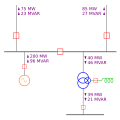
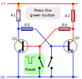
A circuit diagram (or: wiring diagram, electrical diagram, elementary diagram, electronic schematic) is a graphical representation of an electrical circuit...
12 KB (1,307 words) - 11:08, 20 January 2024
A wiring diagram is a simplified conventional pictorial representation of an electrical circuit. It shows the components of the circuit as simplified shapes...
4 KB (462 words) - 12:39, 11 July 2025
Schematic (redirect from Schematic diagram)
physical details. In an electronic circuit diagram, the layout of the symbols may not look anything like the circuit as it appears in the physical world:...
8 KB (829 words) - 20:09, 21 March 2025
Electronic symbol (redirect from Circuit symbol)
batteries, resistors, and transistors, in a schematic diagram of an electrical or electronic circuit. These symbols are largely standardized internationally...
24 KB (1,793 words) - 03:43, 25 June 2025
Logic gate (redirect from Logic circuit)
and outputs negated. Use of these alternative symbols can make logic circuit diagrams much clearer and help to show accidental connection of an active high...
42 KB (3,649 words) - 12:03, 8 July 2025
A diagram is a symbolic representation of information using visualization techniques. Diagrams have been used since prehistoric times on walls of caves...
16 KB (1,032 words) - 06:35, 5 March 2025
the software ensures consistency between the circuit and the layout. A component in the circuit diagram comprises several elements: A symbol, which typically...
15 KB (1,614 words) - 23:29, 29 April 2025
MR 1796805. Q-circuit Archived 2019-03-23 at the Wayback Machine is a macro package for drawing quantum circuit diagrams in LaTeX. Quantum Circuit Simulator...
24 KB (3,343 words) - 18:11, 15 December 2024
engineering, a node is any region or joining point on a circuit between two circuit elements. In circuit diagrams, connections are ideal wires with zero resistance...
4 KB (428 words) - 12:38, 10 July 2025
concerned with the physical layout of components in a circuit, nor with their positions on a circuit diagram; similarly to the mathematical concept of topology...
47 KB (6,594 words) - 10:24, 24 May 2025
analog circuits are wires, resistors, capacitors, inductors, diodes, and transistors. Analog circuits are very commonly represented in schematic diagrams, in...
8 KB (1,217 words) - 12:19, 18 March 2025
Thyristor-controlled reactor (section Circuit diagram)
reactive power provided by the TCR. "Thyristor Controlled Reactor: Circuit Diagram | PDF | Electrical Engineering | Electromagnetism". Scribd. Retrieved...
5 KB (816 words) - 12:59, 20 August 2024
sold commercially but is implemented in various ways by active circuits. The circuit diagram shows one common implementation. The nonlinear resistor is implemented...
13 KB (1,363 words) - 15:01, 12 March 2025
exciting admittance Short-circuit test Thévenin's theorem Blocked rotor test Circle diagram Electrical4U. "Open and Short Circuit Test of Transformer | Electrical4u"...
6 KB (1,029 words) - 10:17, 16 May 2024
Electrical network (redirect from Electrical circuit)
Memristor Open-circuit voltage Short circuit Voltage drop Circuit diagram Schematic Netlist Network analysis (electrical circuits) Mathematical methods in electronics...
10 KB (1,221 words) - 13:54, 15 July 2025
Thyristor-switched capacitor (section Circuit diagram)
frequency of the AC system The TSC forms an inductor-capacitor (LC) resonant circuit with a characteristic frequency of : f t s c = 1 2 π C t s c L t s c {\displaystyle...
10 KB (1,480 words) - 16:23, 26 March 2023
which when not in use was secured in a cradle in the base unit. The circuit diagram of the model 202 shows the direct connection of the transmitter to...
60 KB (6,239 words) - 08:03, 29 June 2025
alternating current circuits). The single-line diagram has its largest application in power flow studies. Electrical elements such as circuit breakers, transformers...
7 KB (800 words) - 21:43, 23 June 2025
phase-shift oscillator shown in the diagram uses an operational amplifier (op-amp), three capacitors and four resistors. The circuit's modeling equations for the...
6 KB (1,056 words) - 23:34, 23 May 2024
Wheatstone bridge (redirect from Wheatstone bridge circuit)
Wheatstone bridge is an electrical circuit used to measure an unknown electrical resistance by balancing two legs of a bridge circuit, one leg of which includes...
11 KB (1,572 words) - 15:32, 12 July 2025
Flip-flop (electronics) (redirect from Bistable circuit)
the two stages are connected in a non-inverting loop although the circuit diagram is usually drawn as a symmetric cross-coupled pair (both the drawings...
57 KB (7,211 words) - 23:43, 5 June 2025
source, or relaxes from an excited state. The band diagram may be shown connected to a circuit diagram showing how bias voltages are applied, how charges...
10 KB (1,365 words) - 00:19, 17 March 2025
electrical circuit Circuit diagram, a graphical representation of an electrical circuit Digital circuit, uses discrete signal levels Electronic circuit, contains...
5 KB (616 words) - 11:29, 22 May 2025
As electrons flow from one half-cell to the other through an external circuit, a difference in charge is established. If no ionic contact were provided...
20 KB (2,234 words) - 01:16, 3 July 2025
An LC circuit, also called a resonant circuit, tank circuit, or tuned circuit, is an electric circuit consisting of an inductor, represented by the letter...
32 KB (5,496 words) - 21:42, 13 July 2025
facilities to apply the very high power levels representative of a fault on an interconnected grid system. Open-circuit test Blocked rotor test Circle diagram...
3 KB (431 words) - 13:31, 4 October 2024
Low-pass filter (redirect from Passive integrator circuit)
behavior in the time domain, and then discretizing the model. From the circuit diagram to the right, according to Kirchhoff's Laws and the definition of capacitance:...
32 KB (4,696 words) - 20:25, 28 February 2025
connection in the printed circuit board, but the layout does. To make an analogy to the map making world, a block diagram is similar to a highway map...
6 KB (742 words) - 16:11, 22 October 2023
Karnaugh map (redirect from Karnaugh diagram)
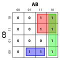
A Karnaugh map (KM or K-map) is a diagram that can be used to simplify a Boolean algebra expression. Maurice Karnaugh introduced the technique in 1953...
30 KB (3,588 words) - 17:11, 17 March 2025
involves synthesising on paper a schematic circuit diagram, an abstract electrical or electronic circuit that will meet the specifications. A calculation...
19 KB (2,341 words) - 06:18, 5 June 2025


