Timing diagram may refer to: Digital timing diagram Timing diagram (Unified Modeling Language) Time–distance diagram This disambiguation page lists articles...
358 bytes (48 words) - 23:31, 7 December 2021
A timing diagram in Unified Modeling Language 2.5.1 is a specific type of interaction diagram, where the focus is on timing constraints. Timing diagrams...
1 KB (140 words) - 13:28, 1 June 2024
A digital timing diagram represents a set of signals in the time domain. A timing diagram can contain many rows, usually one of them being the clock....
4 KB (447 words) - 20:58, 15 May 2025
A diagram is a symbolic representation of information using visualization techniques. Diagrams have been used since prehistoric times on walls of caves...
15 KB (1,032 words) - 04:56, 17 July 2025

types of interaction diagrams: Sequence diagram Communication diagram Interaction overview diagram Timing diagram A Communication diagram models the interactions...
3 KB (271 words) - 01:18, 15 November 2024

In software engineering, a sequence diagram shows process interactions arranged in time sequence. This diagram depicts the processes and objects involved...
7 KB (909 words) - 07:29, 5 March 2025

In Unified Modeling Language (UML), a component diagram depicts how components are wired together to form larger components or software systems. They...
4 KB (371 words) - 03:47, 3 June 2024
In a piston engine, the valve timing is the precise timing of the opening and closing of the valves. In an internal combustion engine those are usually...
5 KB (695 words) - 15:38, 12 March 2025
basis function is shown at the end of the next section in a signal timing diagram. The topmost signal is a BPSK-modulated cosine wave that the BPSK modulator...
42 KB (6,226 words) - 18:36, 8 July 2025

A deployment diagram "specifies constructs that can be used to define the execution architecture of systems and the assignment of software artifacts to...
2 KB (242 words) - 15:18, 22 November 2024

Activity diagrams are graphical representations of workflows of stepwise activities and actions with support for choice, iteration, and concurrency. In...
5 KB (582 words) - 22:25, 25 March 2025
that each periodic process must complete within its period. In the timing diagram, the columns represent time slices with time increasing to the right...
18 KB (2,418 words) - 10:49, 25 July 2025

In object-oriented programming, an object diagram in the Unified Modeling Language (UML) is a diagram that shows a complete or partial view of the structure...
7 KB (779 words) - 12:15, 1 January 2025

Timing diagram over one revolution for angle, angular velocity, angular acceleration, and angular jerk...
35 KB (4,223 words) - 21:46, 21 July 2025
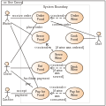
A use case diagram is a graphical depiction of a user's possible interactions with a system. A use case diagram shows various use cases and different types...
4 KB (436 words) - 23:02, 4 November 2024

In software engineering, a class diagram in the Unified Modeling Language (UML) is a type of static structure diagram that describes the structure of a...
19 KB (2,099 words) - 07:40, 5 March 2025
Composite structure diagram in the Unified Modeling Language (UML) is a type of static structure diagram that shows the internal structure of a class and...
6 KB (732 words) - 19:48, 24 August 2024
Unified Modeling Language (redirect from UML Diagram)
many types of diagrams which can be roughly divided into three main groups: behavior diagrams, interaction diagrams, and structure diagrams. The creation...
27 KB (2,974 words) - 14:02, 29 June 2025
the circuit. This time is called a propagation delay. As of 2021[update], timing of modern synchronous ICs takes significant engineering efforts and sophisticated...
57 KB (6,031 words) - 23:14, 11 July 2025
I²C (section Timing diagram)
serial communication, which are distinguished from data bits only by their timing.) The controller is initially in controller transmit mode by sending a START...
78 KB (9,040 words) - 10:58, 4 July 2025
Serial Peripheral Interface (section Timing variations)
respectively, a convention most vendors have also adopted. The SPI timing diagram shown is further described below: CPOL represents the polarity of the...
51 KB (5,946 words) - 13:05, 16 July 2025

onto a block diagram. Other software WDTs are typically custom-designed to meet specific requirements. Every software WDT depends on a timing reference to...
23 KB (2,881 words) - 03:48, 2 April 2025
updated terms master and slave to controller and target. As shown in the diagram, the protocol requires the following lines: Serial clock (SCK), a.k.a....
9 KB (915 words) - 22:51, 11 June 2025

reaching count 10). Schematic diagram of a 4-bit asynchronous BCD decade counter constructed from toggle flip-flops Timing diagram of a 4-bit asynchronous BCD...
45 KB (5,935 words) - 19:19, 9 July 2025

nodes that can contain interaction diagrams. The interaction overview diagram is similar to the activity diagram, in that both visualize a sequence of...
2 KB (240 words) - 03:08, 3 June 2024

A package diagram in the Unified Modeling Language depicts "specializations for Models and for Profiles that organize extensions to UML." In addition...
5 KB (549 words) - 21:39, 19 March 2025

Unified Modeling Language in the field of software engineering, a profile diagram operates at the metamodel level to show stereotypes as classes with the...
2 KB (153 words) - 10:46, 4 June 2024
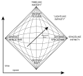
theoretical physics, a Penrose diagram (named after mathematical physicist Roger Penrose) is a two-dimensional diagram capturing the causal relations...
10 KB (1,198 words) - 15:12, 23 June 2025

or digital circuit. A logic analyzer may convert the capture into timing diagrams, protocol decodes, state machine traces, opcodes, or may correlate...
9 KB (1,189 words) - 08:31, 16 April 2025

of the desmodromic system is to force the valves to comply with the timing diagram as consistently as possible. In this way, any lost energy is negligible...
20 KB (2,564 words) - 00:08, 13 July 2025